![Endpoint Security Software 2026: Enterprise Solutions Compared [Buyer's Guide]](https://bitsfrombytes.com/wp-content/uploads/2026/04/endpoint-security-software-2026-complete-guide-110x110.webp)


This page preserves the original G-Code Reference Guide for 3D Printing documentation from the Bits From Bytes wiki (2008-2012).
The Language That Brings 3D Models to Life
G-Code represents the fundamental communication protocol between 3D design software and physical printers. Originally developed in the 1950s for numerical control (NC) machining, this instruction language has become the universal standard for desktop 3D printing, enabling precise control over every aspect of the fabrication process.
This comprehensive guide preserves historical G-Code implementations from the early days of desktop 3D printing while providing modern context and applications. Whether you’re troubleshooting a vintage RapMan 3.1 printer, optimizing contemporary firmware like Marlin or RepRapFirmware, or seeking to understand the fundamental instructions that transform digital models into physical objects, this reference provides authoritative documentation.
G-Code serves as the machine-readable instruction set that directs 3D printers through coordinated movements, temperature control, extrusion parameters, and countless other functions necessary for successful prints. Understanding these commands unlocks advanced printer control, enables troubleshooting, and allows precise customization beyond what standard slicing software provides.
Understanding G-Code Fundamentals
What Is G-Code?
G-Code (RS-274), formally known as RS-274, constitutes the most widely used numerical control programming language in desktop manufacturing. The language consists primarily of commands beginning with “G” (hence the name) or “M” (machine-specific codes), each followed by parameters that define specific actions the printer should execute.
Unlike high-level programming languages, G-Code operates sequentially—the firmware reads and executes each line in order, from the file’s beginning to its end. This straightforward structure makes G-Code accessible even to non-programmers, though mastery requires understanding the nuanced interactions between commands.
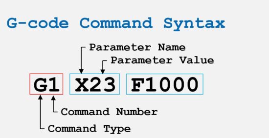
Anatomy of a G-Code Line
A typical G-Code instruction follows this structure:
gcode
G1 X50.5 Y20.3 Z0.2 E0.45 F1500Breaking down this command:
- G1: The command type (coordinated linear move)
- X50.5: Target X-axis position (50.5mm)
- Y20.3: Target Y-axis position (20.3mm)
- Z0.2: Target Z-axis position (0.2mm layer height)
- E0.45: Extrusion amount (0.45mm of filament)
- F1500: Feed rate (1500mm/minute movement speed)
Comments can be added after semicolons, allowing documentation within G-Code files without affecting printer operations. Some firmware also supports CNC-style round bracket comments for compatibility with industrial CNC machines.
Line Numbers and Checksums
Professional G-Code implementations may include line numbers and checksums for error detection:
gcode
N3 T0*57 ; This is a comment
N4 G92 E0*67 ; So is this
N5 G28*22
If present, line numbers should be the first field in each line, typically incrementing by 1 sequentially. RepRap firmware expects this sequential increment, flagging any discontinuity as an error. For G-Code files stored on SD cards, line numbers are usually omitted to conserve storage space and improve readability.
G-Code Generation Methods
Slicing Software (Primary Method)
The most common method for generating G-Code involves slicing software such as Slic3r, Skeinforge, Cura, or PrusaSlicer. These programs import CAD models, slice them into layers, and output the precise G-Code required to print each layer.
Advantages of slicers:
- Automated toolpath generation
- Pre-configured printer profiles
- Material-specific optimizations
- Minimal technical knowledge required
- Rapid iteration from design to print
Historical Context:
During the early desktop 3D printing era (2007-2012), Skeinforge emerged as the dominant slicing engine, powering everything from DIY RepRap builds to commercial machines like the Bits From Bytes RapMan series. BfB Axon software provided a user-friendly frontend for Skeinforge, making G-Code generation accessible to educational institutions and hobbyists.
Modern slicers like PrusaSlicer, Cura, and Simplify3D have built upon these foundations, offering more sophisticated features while maintaining G-Code compatibility with legacy hardware.
Low-Level Libraries (Advanced Control)
Libraries like mecode provide programmatic G-Code generation, giving developers precise control over toolpaths. This approach suits specialized applications where conventional slicing algorithms fall short—for example, generating support structures for complex overhangs, creating custom infill patterns, or implementing experimental printing techniques.
Manual G-Code Writing (Calibration and Testing)
Writing G-Code manually remains the best approach for calibration routines, test patterns, and firmware diagnostics. A few strategically written lines can test specific printer behaviors without generating full print files.
Example manual calibration routine:
gcode
G28 ; Home all axes
G1 Z10 F1500 ; Lift nozzle 10mm
G1 X50 Y50 F3000 ; Move to center
M109 S200 ; Heat and wait for extruder
G1 E10 F100 ; Extrude 10mm slowly to test flow
M104 S0 ; Turn off heater
Essential Movement Commands
G0 and G1: Linear Movement
G0 – Rapid Positioning (Non-printing Move)
gcode
G0 X100 Y100 Z10Moves the toolhead to the specified coordinates at maximum speed without extruding material. Historically used for rapid repositioning between print areas.
G1 – Coordinated Linear Move (Printing Move)
gcode
G1 X100 Y100 Z0.2 E0.5 F1500Performs a coordinated linear move where all axes reach their target positions simultaneously. When the E (extruder) parameter is included, material extrudes during the move, creating the printed object layer by layer.
Parameters:
- X: X-axis target position (mm)
- Y: Y-axis target position (mm)
- Z: Z-axis target position (mm)
- E: Extrusion amount (mm of filament)
- F: Feed rate (mm/minute)
Modern Practice:
Contemporary 3D printer firmware treats G0 and G1 identically in most cases, with the convention that G0 indicates travel moves and G1 indicates printing moves. The feed rate (F) persists between commands until explicitly changed.
G28: Homing
gcode
G28 ; Home all axes
G28 X Y ; Home only X and Y axes
G28 Z ; Home only Z axis
Directs the printer to execute its homing sequence, moving each specified axis until it contacts its endstop switch. This establishes known reference positions (typically 0,0,0) that all subsequent moves reference.
Most print files begin with G28 to ensure the printer starts from a consistent, known location. This command is also useful for moving axes out of the way after printing, facilitating part removal.
G29: Bed Leveling
gcode
G29 ; Probe bed and generate meshTriggers automatic bed leveling sequences. The specific behavior depends on firmware and probe configuration, but typically involves:
- Probing multiple points across the build surface
- Generating a height map of bed topology
- Applying compensation during printing to account for surface variations
Modern printers with automatic bed leveling rely heavily on G29 to achieve optimal first-layer adhesion across slightly uneven build surfaces.
G90 and G91: Positioning Modes
G90 – Absolute Positioning
gcode
G90 ; Set to absolute mode
G1 X100 Y50 ; Move to absolute position (100, 50)
In absolute positioning, all coordinates reference the homing position. Moving to X100 means moving to 100mm from the origin, regardless of current position.
G91 – Relative Positioning
gcode
G91 ; Set to relative mode
G1 X10 Y5 ; Move 10mm in X and 5mm in Y from current position
In relative positioning, coordinates represent movements relative to the current position. X10 means “move 10mm in the positive X direction” rather than “move to the 10mm position.”
Best Practices:
Most slicers default to absolute positioning (G90) for clarity and error reduction. Relative positioning finds use in custom start/end G-Code sequences and manual operations.
Temperature Control Commands
M104: Set Extruder Temperature (Non-Blocking)
gcode
M104 S200 ; Set extruder target to 200°C, don't waitSets the extruder target temperature and continues executing subsequent commands immediately without waiting for the temperature to stabilize. Useful for starting the heating process while performing other initialization tasks.
M109: Set Extruder Temperature and Wait
gcode
M109 S210 ; Set extruder to 210°C and wait until reachedSets the extruder target temperature and pauses G-Code execution until the temperature stabilizes within acceptable tolerance. Critical for ensuring proper extrusion temperature before printing begins.
Historical Note:
Early Bits From Bytes RapMan printers required careful temperature calibration, with optimal ABS extrusion occurring at 247-248°C depending on specific machine thermistor calibration. Even 2°C variations significantly affected print quality.
M140: Set Heated Bed Temperature (Non-Blocking)
gcode
M140 S60 ; Set bed to 60°C, continue immediatelySets the heated bed target temperature without waiting. Typically used early in startup sequences to begin bed heating while the nozzle heats simultaneously.
M190: Set Heated Bed Temperature and Wait
gcode
M190 S60 ; Set bed to 60°C and waitSets heated bed temperature and pauses until the target is reached. Ensures proper bed temperature for first-layer adhesion before printing commences.
M105: Report Temperatures
gcode
M105 ; Request current temperaturesQueries the printer for current extruder and bed temperatures. The firmware responds with current and target temperatures for all heaters, enabling monitoring and verification.
Extrusion Control Commands
E-Axis: The Fourth Dimension
In 3D printing, the extruder functions as a fourth axis, with E values controlling filament feed. Two modes determine how E coordinates are interpreted:
M82 – Absolute Extrusion Mode
gcode
M82 ; Set extruder to absolute mode
G1 X10 Y10 E5.0
G1 X20 Y20 E10.0 ; Total extruded: 10mm
E values represent total filament extruded since homing or reset. Each command specifies absolute extrusion position.
M83 – Relative Extrusion Mode
gcode
M83 ; Set extruder to relative mode
G1 X10 Y10 E0.5
G1 X20 Y20 E0.5 ; Each move extrudes 0.5mm
E values represent the amount to extrude during each specific move. Most modern slicers (particularly PrusaSlicer) default to relative extrusion for improved precision and reduced accumulated error.
G92: Set Position
gcode
G92 E0 ; Reset extruder position to zeroSets the current position for specified axes without moving. Commonly used to reset the extruder position counter (E0) at the beginning of prints or after retraction sequences.
Usage in Start G-Code:
gcode
G28 ; Home all axes
G92 E0 ; Reset extruder position
G1 Z2.0 F3000 ; Move Z up
G1 X10 Y10 F5000 ; Move to start position
G1 Z0.28 F5000 ; Move to first layer height
G92 E0 ; Reset again before printing
G10 and G11: Firmware Retraction
Some firmware supports simplified retraction commands:
G10 – Retract
gcode
G10 ; Perform firmware-configured retractionG11 – Unretract (Prime)
gcode
G11 ; Reverse retraction, prime nozzleThese commands execute retraction sequences defined in firmware settings, simplifying G-Code generation and allowing runtime retraction adjustments without re-slicing.
Fan and Cooling Commands
M106: Set Fan Speed
gcode
M106 S255 ; Set fan to maximum speed (255 = 100%)
M106 S128 ; Set fan to 50% speed
M106 S0 ; Turn fan off
Controls print cooling fan speed. The S parameter ranges from 0 (off) to 255 (maximum), representing PWM duty cycle percentage.
Material Considerations:
- PLA: Benefits from active cooling (S200-255) for overhangs and bridges
- ABS: Minimal cooling (S0-100) to prevent warping and layer delamination
- PETG: Moderate cooling (S100-150) balances layer adhesion and overhang quality
M107: Fan Off
gcode
M107 ; Turn off all print cooling fansConvenience command equivalent to M106 S0, turning cooling fans completely off.
Advanced Calibration and Configuration
M92: Set Steps Per Unit
gcode
M92 X80 Y80 Z400 E95 ; Set steps/mm for all axesConfigures stepper motor steps per millimeter for each axis. Critical for dimensional accuracy, ensuring the printer moves exactly the distances commanded in G-Code.
Extruder Calibration:
The E-axis steps/mm value directly affects extrusion accuracy. Incorrect values cause over-extrusion (blobs, poor surface finish) or under-extrusion (gaps, weak parts).
Calibration procedure:
- Mark filament 120mm above extruder
- Command extruder to feed 100mm:
G1 E100 F100 - Measure remaining distance to mark
- Calculate new steps:
new_steps = current_steps × (100 / actual_distance) - Apply with M92 and save to EEPROM with M500
M201: Maximum Acceleration
gcode
M201 X1000 Y1000 Z100 E5000 ; Set max acceleration (mm/s²)Defines maximum acceleration values for each axis. Higher values enable faster prints but may introduce ringing artifacts or mechanical strain.
M203: Maximum Feed Rate
gcode
M203 X300 Y300 Z12 E120 ; Set max speeds (mm/s)Establishes speed limits for each axis. The firmware will never exceed these values, regardless of F parameters in G1 commands.
M204: Acceleration Profiles
gcode
M204 P1000 R1000 T1000 ; P=printing, R=retract, T=travelSets different acceleration values for printing moves, retraction moves, and travel moves, allowing fine-tuned acceleration profiles that balance speed and quality.
M500/M501/M502/M503: EEPROM Management
M500 – Save Settings to EEPROM
gcode
M500 ; Save current configuration to non-volatile memoryM501 – Load Settings from EEPROM
gcode
M501 ; Load saved configurationM502 – Restore Factory Defaults
gcode
M502 ; Reset all settings to firmware defaultsM503 – Report Settings
gcode
M503 ; Display current configurationThese commands manage persistent firmware configuration. After calibrating steps/mm, acceleration, or PID values, M500 ensures settings survive power cycles.
Historical G-Code: Bits From Bytes Era
BFB-Specific Implementations
Bits From Bytes printers utilized G-Code with some manufacturer-specific conventions. Files typically carried the .bfb extension but contained standard G-Code internally.
Typical BFB File Header:
gcode
^Axon version: 2.1.0
^Checksum: YES
^Time: 1234
^Ex1: PLA red translucent
^Ex2: ABS green
M227 P3200 S3200
M105
M113 S1.0
M108 S600.0
The carat (^) prefix denoted metadata comments specific to Axon software, providing print time estimates and material information for user reference.
Skeinforge-Generated G-Code
Skeinforge, the dominant slicing engine for early RepRap and commercial printers like the RapMan, produced highly customizable G-Code with extensive control over:
- Raft generation and adhesion
- Infill patterns and density
- Support structure generation
- Temperature profiles per layer
- Wipe and oozebane (anti-stringing) routines
Legacy Parameter Example:
gcode
M201 ; Start of Skeinforge settings comment
(Layer thickness: 0.25mm)
(Perimeter width: 0.6mm)
(Infill: 25% rectilinear)
While Skeinforge has been largely superseded by modern slicers, understanding its G-Code structure remains valuable for maintaining vintage printers and interpreting legacy print files.
Modern G-Code: Contemporary Firmware
Marlin Firmware
Marlin represents the most widely used 3D printer firmware, running on the majority of consumer desktop printers. It implements extensive G-Code commands beyond the basic RepRap set, including:
Linear Advance (M900)
gcode
M900 K0.08 ; Set Linear Advance K factorCompensates for pressure buildup in the nozzle, improving dimensional accuracy and reducing artifacts at direction changes.
Babystepping (M290)
gcode
M290 Z0.05 ; Adjust Z height by 0.05mm without homingAllows real-time Z-axis adjustments during printing, useful for compensating first-layer adhesion without re-leveling the bed.
RepRapFirmware (Duet)
RepRapFirmware powers Duet controller boards, emphasizing “G-Code everywhere” philosophy where configuration, operation, and automation all use G-Code commands.
Notable Features:
- Object-model expressions in parameters:
{2+2} - Conditional G-Code execution
- Comprehensive sensor integration
- Network-based control and monitoring
Configuration Example:
gcode
M308 S0 P"temp0" Y"thermistor" A"Hotend" B4725 C7.06e-8
M950 H0 C"out0" T0
M307 H0 B0 S1.00
M143 H0 S280
Klipper Firmware
Klipper takes a unique approach, running intensive calculations on a host computer (typically Raspberry Pi) while relegating the printer’s microcontroller to simple, high-speed motion execution.
Extended G-Code Commands:
gcode
PRESSURE_ADVANCE ADVANCE=0.05 ; Set pressure advance
INPUT_SHAPER_CALIBRATE ; Auto-tune input shaping
TUNING_TOWER COMMAND=SET_VELOCITY_LIMIT PARAMETER=ACCEL START=1000 FACTOR=100 BAND=5
Klipper’s resonance compensation and pressure advance significantly improve print quality on CoreXY and delta printers.
Troubleshooting with G-Code
Diagnosing Print Quality Issues
Under-Extrusion:
Test extrusion multiplier by sending controlled extrusion commands:
gcode
M83 ; Relative extrusion
G1 E100 F100 ; Extrude 100mm slowly
Measure actual filament consumed. If significantly different from 100mm, recalibrate E-steps (M92 E value).
Temperature-Related Problems:
Create temperature towers using G-Code commands:
gcode
M104 S210 ; Start at 210°C
; Print 20 layers
M104 S205 ; Reduce to 205°C
; Print 20 more layers
M104 S200 ; Reduce to 200°C
Examine each temperature segment for optimal quality, identifying the ideal temperature for your specific filament.
First Layer Adhesion:
Manual bed leveling verification sequence:
gcode
G28 ; Home all axes
G1 Z0 ; Move to Z zero
; Use paper to check nozzle gap at multiple points
G1 X50 Y50 ; Center
G1 X10 Y10 ; Front left
G1 X200 Y10 ; Front right
G1 X200 Y200 ; Back right
G1 X10 Y200 ; Back left
Emergency Commands
M112 – Emergency Stop
gcode
M112 ; Immediate shutdown of all heaters and motorsHalts all operations instantly. Requires power cycle or firmware reset to resume. Use only for genuine emergencies—thermal runaway, mechanical collision, or imminent failure.
M999 – Reset (Marlin)
gcode
M999 ; Restart firmware after M112 emergency stopCustom Start and End G-Code
Start G-Code Best Practices
A well-crafted start sequence ensures print success:
gcode
G28 ; Home all axes
G29 ; Bed mesh leveling (if available)
G92 E0 ; Reset extruder position
M190 S60 ; Heat bed and wait
M109 S210 ; Heat nozzle and wait
G1 Z2.0 F3000 ; Move Z up
G1 X10 Y10 F5000 ; Move to start position
G1 Z0.28 F5000 ; First layer height
G92 E0 ; Reset extruder
G1 X10 Y200 Z0.28 F1500 E15 ; Prime line
G92 E0 ; Reset extruder again
This sequence:
- Homes axes for reference
- Levels bed for adhesion
- Heats components to target temperatures
- Primes the nozzle to ensure flow
- Resets extrusion counter before printing
End G-Code Best Practices
Proper print completion prevents failures and facilitates part removal:
gcode
G91 ; Relative positioning
G1 E-2 F2700 ; Retract
G1 E-2 Z0.2 F2400 ; Retract and raise Z
G1 X5 Y5 F3000 ; Wipe out
G1 Z10 ; Raise Z more
G90 ; Absolute positioning
G1 X0 Y220 ; Present print
M106 S0 ; Turn off fan
M104 S0 ; Turn off hotend
M140 S0 ; Turn off bed
M84 ; Disable steppers
This sequence:
- Retracts to prevent oozing
- Lifts nozzle away from print
- Positions bed for easy part removal
- Safely powers down heaters
- Disables motors to save power
G-Code Analysis and Optimization
Reading Slicer-Generated G-Code
Modern slicers embed extensive metadata in comments:
gcode
; generated by PrusaSlicer 2.6.0 on 2024-03-15 at 14:23:15 UTC
; external perimeters extrusion width = 0.45mm
; perimeters extrusion width = 0.45mm
; infill extrusion width = 0.45mm
; solid infill extrusion width = 0.45mm
; top infill extrusion width = 0.40mm
Understanding these annotations helps diagnose slicer settings when troubleshooting print quality issues.
Post-Processing G-Code
Advanced users often post-process G-Code for specialized behaviors:
Adding Custom Layer-Change Commands:
python
# Python script to insert commands at layer changes
with open('print.gcode', 'r') as f:
    lines = f.readlines()

output = []
for line in lines:
    if line.startswith(';LAYER:'):
        output.append('M117 ' + line.strip() + '\n')  # Display layer on LCD
        output.append('M300 S1000 P100\n')  # Beep speaker
    output.append(line)

with open('print_modified.gcode', 'w') as f:
    f.writelines(output)
Common post-processing applications include:
- Filament change prompts for multi-color single-extruder prints
- Pause commands for inserting magnets or hardware
- Temperature adjustments between sections
- Custom cooling profiles for specific geometries
G-Code for Different Printer Architectures
Cartesian Printers
Standard XYZ Cartesian geometry (like RapMan 3.1 and most consumer printers) uses straightforward coordinate systems:
gcode
G1 X100 Y50 Z10 ; Direct coordinate controlDelta Printers
Delta architecture requires firmware-level inverse kinematics to convert XYZ coordinates into tower positions. G-Code remains identical, but calibration commands differ:
gcode
M665 R130 L250 B110 H240 ; Set delta parameters
M666 X0 Y0 Z0 ; Set endstop adjustments
CoreXY Printers
CoreXY kinematics use both motors for X and Y movements. While G-Code coordinates remain standard, optimal acceleration and jerk settings differ significantly from Cartesian machines.
Working with Multiple Extruders
Tool Selection Commands
T0, T1, T2… – Select Tool
gcode
T0 ; Select first extruder
T1 ; Select second extruder
Multi-extruder printers require explicit tool selection. Firmware automatically applies tool offset compensation.
Tool Offset Calibration
M218 – Set Hotend Offset
gcode
M218 T1 X33.0 Y0.0 Z0.0 ; Set offset for second extruderPrecise offset calibration ensures proper alignment when switching between extruders mid-print. Test patterns with fine detail printed from each extruder help measure actual offsets.
Dual Extrusion Strategies
Prime Tower Method:
gcode
; Switch to second extruder
T1
G1 X50 Y50 F4000 ; Move to prime tower location
G1 E5 F300 ; Prime extruder
; Resume printing with new material
Prime towers waste some material but ensure consistent extrusion when switching between extruders, particularly important for multi-material or soluble support prints.
Future of G-Code in 3D Printing
G-Code Limitations
While universally adopted, G-Code presents inherent limitations:
- Sequential execution lacks parallelization
- Limited error handling and flow control
- Verbose, leading to large file sizes for complex prints
- No standardization across firmware implementations
Emerging Alternatives
Binary G-Code (.x3g, .3mf):
Some manufacturers have moved toward binary formats encoding the same information more compactly. However, human readability is sacrificed.
High-Level Job Description Languages:
Formats like 3MF embed model geometry, material properties, and printer settings in structured XML, allowing printers to perform slicing independently. This approach remains nascent but shows promise for cloud-based and network-connected manufacturing.
G-Code Extensions
Modern firmware continues extending G-Code capabilities:
- Object model queries (RepRapFirmware)
- Conditional execution and loops (Klipper macros)
- Real-time parameter adjustment during prints
- Advanced sensor integration and closed-loop control
Despite these innovations, core G-Code commands remain remarkably stable, ensuring decades-old printers can still interpret modern G-Code files’ fundamental instructions.
Frequently Asked Questions
What is the difference between G-Code and M-Code?
G-commands primarily handle motion and positioning, while M-commands control machine-specific functions like temperature, fans, and EEPROM. The distinction originated in industrial CNC machining and has been maintained in 3D printing firmware.
Can I edit G-Code files manually?
Yes, G-Code files are plain text and can be edited in any text editor. This enables custom modifications, troubleshooting corrections, and insertion of specialized commands. Always backup original files before editing.
Why do slicers generate such large G-Code files?
Each layer of a print requires hundreds or thousands of movement commands, creating files that often reach tens of megabytes for complex prints. Removing comments and using relative positioning can reduce file size, though storage is rarely a practical limitation with modern SD cards.
Is G-Code the same for all 3D printers?
Core commands remain consistent, but firmware-specific extensions vary significantly. Marlin, RepRapFirmware, Klipper, and proprietary firmware each implement unique features. Always consult your printer’s firmware documentation for supported commands.
How do I find optimal G-Code settings for my printer?
Start with slicer profiles for similar printers, then iteratively adjust based on print quality. Temperature towers, flow rate calibration cubes, and retraction tests provide measurable data for optimization. Document successful settings for reproducibility.
Can modern slicers work with vintage 3D printers like the RapMan?
Yes, with proper configuration. Modern slicers like PrusaSlicer and Cura can generate compatible G-Code for legacy printers by setting correct build volumes, firmware types, and custom start/end G-Code sequences. Historical slicers like Skeinforge remain most reliable for some vintage hardware.
What G-Code commands are essential for beginners?
Focus on understanding G28 (homing), G1 (movement), M104/M109 (extruder temperature), M140/M190 (bed temperature), and M106/M107 (fan control). These commands appear in virtually every print file and cover fundamental printer control.
How can I test G-Code without printing?
Most printer control software (OctoPrint, Pronterface, Repetier-Host) allows sending individual commands to observe printer behavior. Additionally, G-Code visualization tools like gcode.ws render toolpaths visually without requiring physical hardware.
What should I do if G-Code produces unexpected results?
Verify firmware compatibility—some commands behave differently across firmware versions. Check coordinate mode (absolute vs. relative) with G90/G91. Examine temperature settings and feed rates. Use M503 to review current printer configuration against expected values.
Are there G-Code security concerns?
Malicious G-Code could potentially overheat components, command movements that damage hardware, or erase firmware settings. Only execute G-Code from trusted sources, and review files from unknown origins before printing, particularly checking temperature commands and movement boundaries.
Conclusion: Mastering the Language of Digital Fabrication
G-Code represents the foundational language connecting digital design to physical manufacturing in desktop 3D printing. From its origins in 1950s numerical control machining through its adoption by the RepRap project and subsequent standardization across consumer 3D printers, G-Code has proven remarkably durable and adaptable.
Understanding G-Code transcends mere technical knowledge—it empowers makers to troubleshoot problems, optimize print quality, customize behaviors, and push hardware beyond default capabilities. Whether maintaining historical printers like the RapMan 3.1, fine-tuning contemporary machines, or developing custom printing techniques, G-Code literacy unlocks the full potential of desktop additive manufacturing.
As 3D printing technology continues evolving, G-Code’s human-readable structure and sequential simplicity ensure its relevance. While future formats may emerge, the core commands documented here will remain essential knowledge for anyone seeking to truly understand how 3D printers transform imagination into reality, one precisely controlled movement at a time.
Further Reading and Resources
On This Site:
- Skeinforge Complete Guide – Historical slicing software documentation
- RapMan 3.1 Documentation – Comprehensive printer guide
- 3D Printing Teaching Resources – Educational applications
- Materials Guide – Filament properties and settings
External Resources:
- RepRap G-Code Wiki – Comprehensive command reference
- Marlin Firmware Documentation – Marlin-specific commands
- Duet RepRapFirmware G-Code Dictionary – RepRapFirmware reference
- Simplify3D G-Code Tutorial – Beginner-friendly introduction
- All3DP G-Code Commands Guide – Modern command overview
Historical Documentation:
- EduTech Wiki RapMan G-Code Guide – Practical vintage printer examples
- BfB Axon Documentation – Historical Skeinforge frontend
This documentation preserves G-Code knowledge from the early desktop 3D printing era while providing contemporary context and applications for modern makers, educators, and 3D printing enthusiasts.


